

SOURCE: Published repair instruction of SAF Holland Group
(summarized slightly)
Pivot bushing installation- First part of this post, gave details on removing the pivot bushing. This post is going to go through the steps to install the replacement pivot bushing.
- Remember that the pivot bushing replacement tool is used both for removing the old pivot bushing (removing tool) and to installing the new one (installation tool).
INSTALLATION
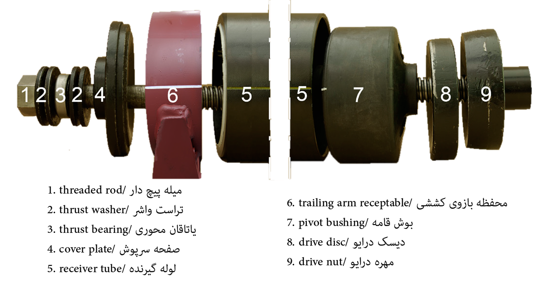
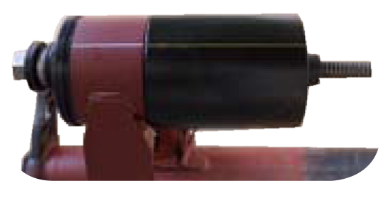
The pivot bushing installation tool consists of a threaded rod (1), two thrust washers (2), a thrust bearing (3), two more thrust washers (2), a cover plate (4), a receiver tube (5), an additional drive disc (8), and a drive nut (9).
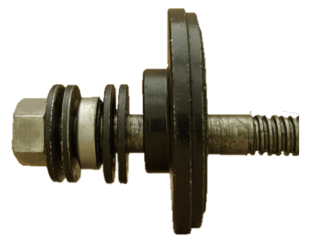
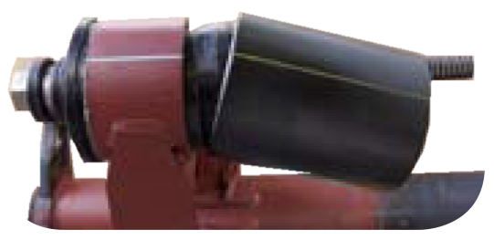
IMPORTANT! The centering ring of the receiver tube is used to center the receiver tube on the trailing arm receptacle. When the installation tool is used, the centering ring must always be positioned against the trailing arm receptacle.
Prior to installing the pivot bushing in the trailing arm receptacle, assemble the installation tool by placing the following components on to the threaded rod (1) in the following order (figure 8).
- Two thrust washers (2)
- Thrust bearing (3)
- Two thrust washers (2)
- Cover plate (4)
INSTALLING THE PIVOT BUSHING
- Lubricate the threads on the threaded rod (1).
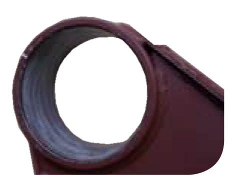
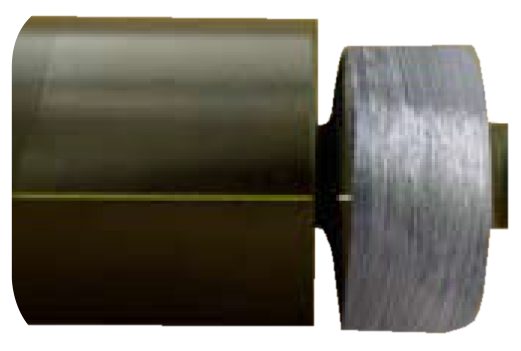
- Apply mounting paste evenly to the internal surface of the receptacle (6) as illustrated in figure 9 and to the external surface of the replacement pivot bushing (7) as shown in figure 10.
3. Use mounting paste P-80, ITEM P5324.
WARNING! Failure to use proper lubricant during pivot bushing installation could reduce vehicle stability which could result in death or serious injury.
- DO NOT lubricate with oil or grease.
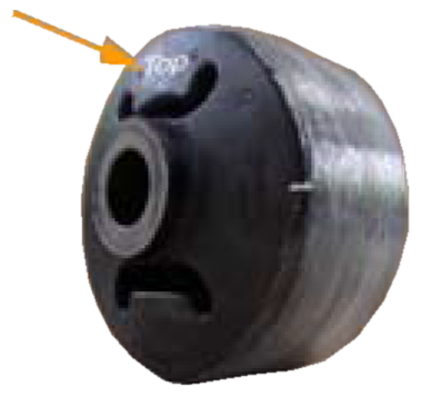
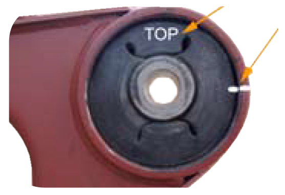
4. Insert the pivot bushing (7) into the receiver tube end (5) opposite of the centering ring. Make sure that the pivot bushing is properly aligned in the receiver tube using the bushing position locator as a reference point (figure 11). The bushing position locator of the replacement bushing must be aligned with the line on the outside of the receiver tube. The orientation index marked “Top” must face upward as illustrated in figure 10. I needed readjust the pivot bushing.
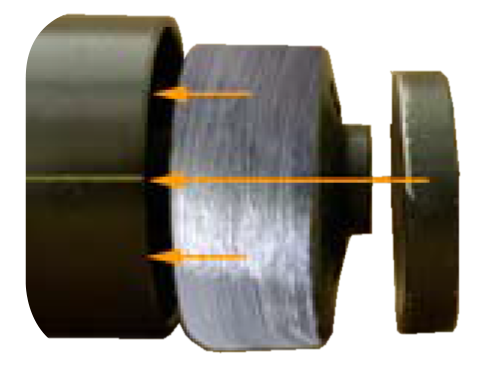
5. Push the pivot bushing (7) and the drive disc (8) completely into the receiver tube (5) as shown in figure 12.
6. Insert the threaded rod (1) of the pre-assembled installation tool from the wheel side through the receptacle, making sure that the cover plate (4) is positioned properly against the receptacle (6) as illustrated in figure 13.
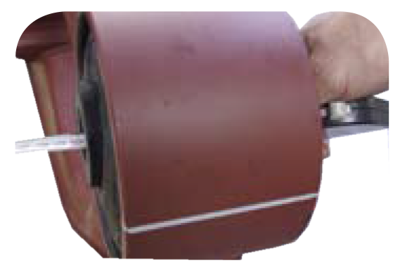
7. Slide the equipped receiver tube (5) over the exposed threaded bolt (1) with the centering ring of the receiver tube facing toward the receptacle (6) until the receiver tube rests squarely on the receptacle. Make sure that the line previously drawn on the external surface of the receptacle is aligned with the line on the receiver tube (figures 14 & 15).
8. Turn the hex-head bolt (1) with a wrench and force the pivot bushing (7) into the receptacle (6) until the receiver tube becomes loose (figure 16).
- Failure to support loose receiver tube may allow it to fall, resulting in minor injury or property damage.
- Prevent that the receiving tube falls to the ground.
9. Remove the receiver tube and continue to turn the threaded rod until the pivot bushing is completely drawn into the receptacle.
10. Disassemble and remove the installation tool.
11. Check the spring center and readjust as needed.
12. Check the proper orientation of thee pivot bushing. Make sure that the orientation index marked “TOP” (in white color for illustration purposes) faces upward and that the bushing position locator of the replacement bushing is aligned with the bushing orientation line drawn on the outside of the receptacle. If the replacement pivot bushing is not installed properly, remove and reinstall it.
Remove the pivot bushing on the opposite axle side and install a replacement pivot bushing.
FINAL STEPS
- Lift the axle.
- Install and slightly tighten the pivot bolt.
- Install the shock absorber.
- Remove the jacks.
- Apply air pressure to the air suspension system.
- Remove the wheel chocks.
- Adjust the ride height.
- Check the axle alignment of the trailer.
- Tighten the pivot bolt.